An Engineer’s Perspective on Anesthesia Machines

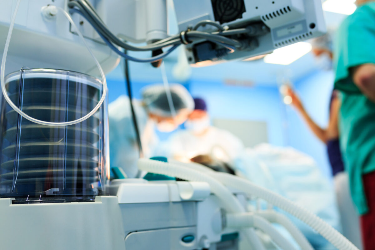
Anesthesia machines are a complex array of mechanical, electrical, and digital components. The safety of anesthesia administration relies on both the primary design of the machine and its safety features. Hence, knowing the basic design of anesthesia machines is a must for all practicing anesthesiologists to understand the modern anesthesia workstation.
The primary function of an anesthesia machine is to provide a gas mixture that is delivered to a breathing system. The machine performs four essential functions: Provides O2, accurately mixes anesthetic gases and vapors, enables patient ventilation and minimizes anesthesia-related risks to patients and staff. [3]
The anesthesia machine can be conveniently divided into three parts:
The high-pressure system, which receives gases at cylinder pressure, reduces pressure. The high-pressure system consists of all parts of the machine which receive gas at cylinder pressure. These include the hanger yoke which connects a cylinder to the machine, the yoke block, used to connect larger-sized cylinders, the cylinder pressure gauge, which indicates the gas pressure in the cylinder and the pressure regulator, which converts a high variable gas pressure into a lower, more constant pressure. These pressure regulators are necessary for the anesthesiologist to maintain a constant flow as the cylinder pressure decreases with use.
The intermediate pressure system receives gases from the regulator or hospital pipeline and delivers them through the flow assembly. The flow meter assembly includes the components of the machine which receive gases at reduced pressures, usually 37-55 PSIG.[4] Modern machines also include O2 pressure fail-safe systems, pipeline inlet connections, pipeline pressure gauges, and ventilator power outlets.
The flow meter assembly controls, measures and indicates the rate of flow of gas passing through it. The flow meter assembly contains valves that control the flow of gas passing through a flow meter. In more modern devices, a monitor control limits the amount of O2 the user can provide to less than 25% of the total flow.
The rate of gas flow depends on the physical characteristics of the gas. Because the annular space is tubular at low flow rates, flow is laminar and viscosity determines the gas flow rate – hence, in accordance with Poiseuille’s law. The annular space simulates an orifice at high flow rates, and turbulent gas flow then depends predominantly on the density of the gas – following Graham’s law.[5]
The low-pressure system takes gases from the flow meters to the machine outlet and also contains the vaporizers.[4] It is the part of the machine downstream the flow meters in which the pressure is slightly above atmospheric. The low-pressure system consists of a back bar where the vaporizers, the backpressure safety devices, and the common gas outlet are mounted.[4] For certain machines, the back bar terminates in a valve which turns in one direction allowing the use of a semi-closed breathing system; in the other types of machines, the back bar transfers the gases into an absorber in the cycle. This unit is sometimes combined with a “Trilene Interlock,” which prevents the trichloroethylene vaporizer from being turned on when a closed circuit is in use and avoids the vaporizer to work without the closed circuit.[1]
[1] Gurudatt C. The basic anaesthesia machine. Indian J Anaesth. 2013;57(5):438–445. doi:10.4103/0019-5049.120138
[3] Sinclair CM, Thadsad MK, Barker I. Modern anaesthetic machines; continuing education in anaesthesia. Crit Care Pain. 2006;6:75–8
[4] Dorsch JA, Dorsch SE. 2nd ed. Baltimore, USA: Williams and Wilkins; 1984. Understanding Anesthesia Equipment, Construction, Care and Complications; pp. 38–76.
[5] Brockwell RC, Andrews JJ. Inhaled anesthetic delivery systems. In: Miller RD, editor. Miller’s Anesthesia. 7th ed. Philadelphia, Pennsylvania: Churchill Livingstone; 2010. pp. 667–716.